Hi Pythonistas!
This is part 2 of the NodeMCU series. In case you haven’t read part 1 click here.
Today, we are going to take input from a switch and toggle the LED accordingly.
Components Required:
NodeMCU
Switch
Breadboard
Wires
Resistor 10K (optional)
Wire the circuit as per diagram below.
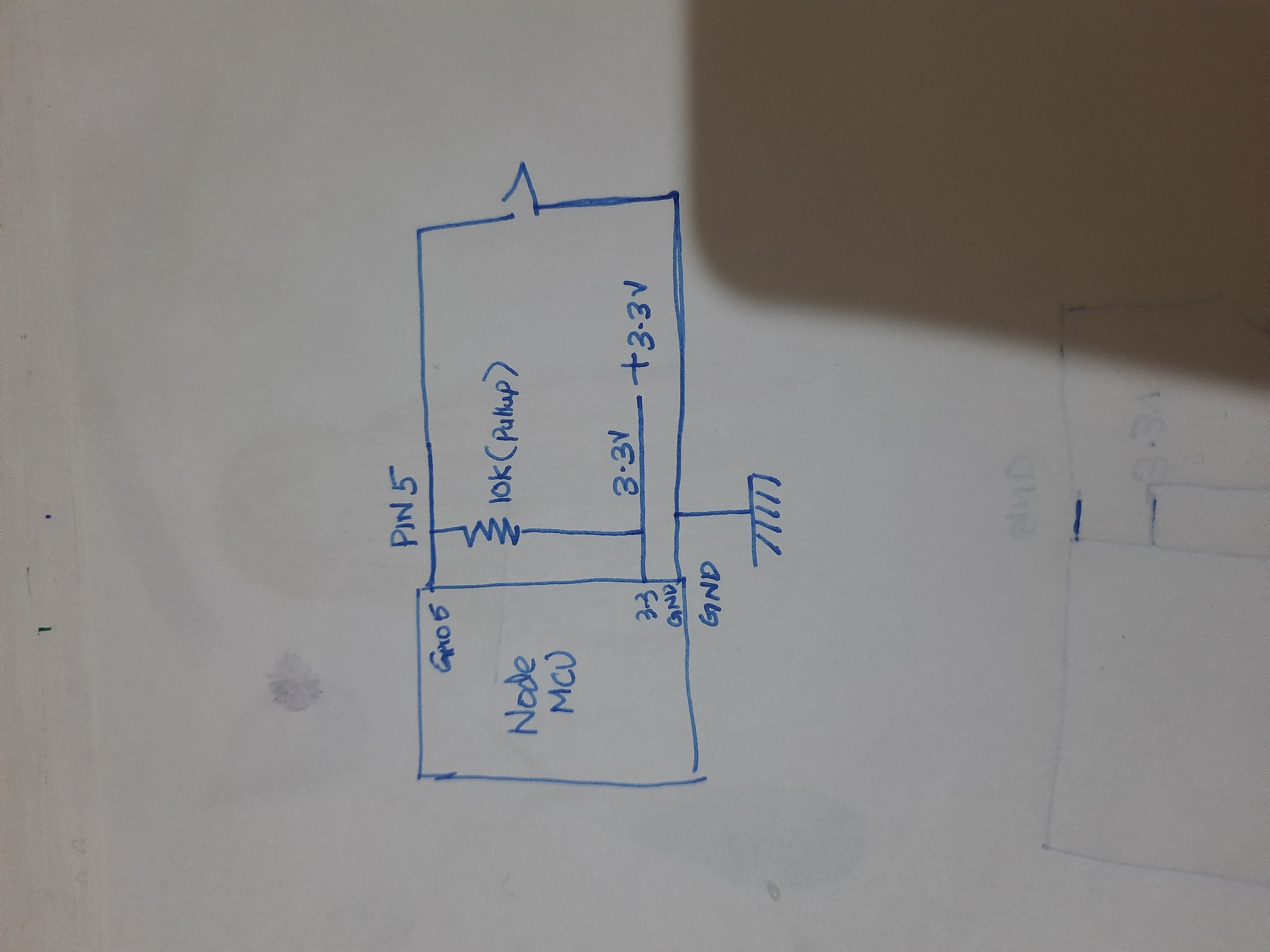
The resistor in the circuit is optional. It can be handled at the code level. We will discuss more on that later in the code section.
Connect NodeMCU to the machine. Open Thonny and then open a new file. Paste the following code
from machine import Pin
from time import sleep

led = Pin(2, Pin.OUT)
led.value(0)

switch = Pin(5, Pin.IN)

while True:
    print("Switch value", switch.value())
    led.value(switch.value())
    sleep(.01)
Let's go through the code line by line and understand what it means.
led = Pin(2, Pin.OUT)This code will set pin 2 as output pin , and the onboard LED is connected to this pin. If you are not using a pull-up resistor we can change the code as given below.
led = Pin(2, Pin.OUT, Pin.PULL_UP)led.value(0)This line will set the value of the pin as off.
switch = Pin(5, Pin.IN)This line is used to set pin 5 as an input pin.
while True:
    print("Switch value", switch.value())
    led.value(switch.value())
    sleep(.01)
This is a finite loop that prints the current state of the switch and sets that state to LED. We have given a 10ms delay after the setting.